A seal that fails in the first hours of service was almost certainly damaged during assembly. A seal that fails after two years was probably not. The distinction is worth making early, because installation damage and wear look nothing alike on the part but are often confused on the service report.
The mechanism is always mechanical: the rubber was cut, stretched, twisted or pinched as it went into the gland.
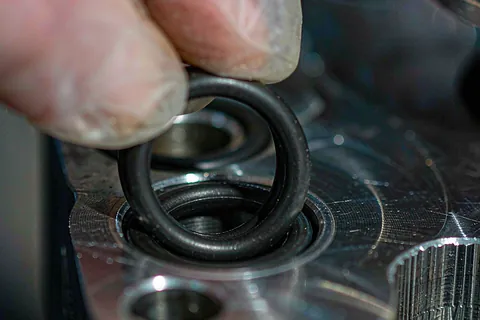
Six ways a ring gets damaged going in
1. A sharp edge at the bore or rod entry
The ring is pushed over an edge that has no chamfer, or a chamfer with a burr on its lip. The cut is clean, crosses the section, and the two faces match when the ring is closed up again — which is why it is often mistaken for a material split.
2. Threads, keyways and splines
Any interrupted surface between the assembly path and the groove will cut a ring that is dragged over it. The damage is a series of nicks along one arc, matching the pitch of the thread or the width of the keyway.
3. Twisting during installation
The ring rolls in the groove as it is pushed in. In dynamic service this becomes spiral failure; statically it shows as diagonal marks and a ring that is not sitting flat in the groove. A twisted ring has uneven squeeze, so it leaks at the point where the twist lifts it off the surface.
4. Over-stretch
Stretching a ring to get it over a diameter permanently reduces its cross-section. At 5 % stretch the section loses a few percent of its height; at 10 % it loses much more, and the ring will not recover fully. A ring installed with heavy stretch is over-squeezed at the ends of the stretch axis and under-squeezed at 90° to it.
5. Dry assembly
Rubber on dry metal has a high coefficient of friction. The ring catches, rolls, or abrades a flat on its surface. In dynamic seals, dry assembly also removes the lubricant film that the seal needs for its first strokes.
6. Contamination
Metal chips, blasting grit, thread sealant fragments and dust in the groove. A single chip under the ring creates a leak path and a stress concentration that starts a cut.
The geometry that prevents it
Four dimensions do most of the work, and they are frequently missing from drawings:
| Feature | Requirement | Why |
|---|---|---|
| Entry chamfer | 15–20°, length at least 1.5 × cross-section | Lets the ring slide in instead of catching on the edge |
| Chamfer lip | Deburred, no sharp transition | The lip is where the cut starts |
| Groove corner radius | 0.005 in minimum at the bottom | Sharp internal corners take a mechanical set and tear on installation |
| Cover or port edges | Radiused or chamfered to the same rule | Ports break into the bore and leave burrs |
For a 0.139 in cross-section, the chamfer should be at least 0.21 in long. On a bore entry that is often longer than the lead-in the designer has allowed, which is why the chamfer is the first thing to check when a rod seal fails early.
run a finger — or better, a cotton bud — around the bore entry and the groove edges before assembly. A cotton bud that snags has found a burr that will cut the ring.
Lubrication: which one, and how much
The assembly lubricant has to be compatible with the system fluid, because a residue stays in the joint. Three practical choices:
- System fluid itself — always compatible, adequate for most static joints.
- Silicone grease — excellent release, but not acceptable in silicone-sensitive systems, in painting operations, or where the fluid must stay clean (hydraulic servo, oxygen).
- Soapy water or dedicated assembly fluid — for water and food-contact joints where a hydrocarbon lubricant is not allowed.
Apply a thin film to the ring and to the bore entry, not a blob in the groove. Excess lubricant can hydraulic-lock a tight gland during assembly and can also migrate to a surface where it interferes with bonding or painting.
Temperature at assembly
A ring at −10 °C is stiff and much more likely to tear. If the assembly area is cold, warm the rings — not above 100 °C for most compounds, and never with a hot air gun aimed at one spot. Warm rubber conforms, cold rubber cracks.
The same logic in reverse applies to shrinking a ring onto a piston: cooling a ring to make it slip over a diameter is a technique for metal, not rubber. Below the compound's glass transition the ring becomes brittle and will crack rather than stretch.
Inspecting for damage you cannot see
Visual inspection catches cuts on the outer surface and misses everything on the sealing face that is against the groove. Three methods find the rest:
- Magnification and light at a low angle. A 10× loupe with raking light shows nicks that are invisible head-on.
- Flex test. Bend the ring double at several points around the circumference. A cut opens; a moulding flaw shows as a line that does not open.
- Pressure decay before installation. For a critical joint, assemble dry and pressurise to a low test pressure, then check decay. This catches a damaged ring before the system is filled.
What the damage pattern tells you
| Pattern | Mechanism | Fix |
|---|---|---|
| One clean cut, faces match | Sharp edge on entry | Chamfer and deburr |
| Series of nicks along an arc | Thread or keyway | Sleeve the thread during assembly |
| Diagonal tears, ring twisted | Rolled during installation or in service | Lubricate, check groove width, reduce squeeze |
| Flat worn spot on one side | Abrasion from dry assembly or rough bore | Lubricate, improve finish |
| Ring cut at a cross-drilled port | Burr at the port | Deburr the port, radius the intersection |
| Ring cracked, not cut | Cold assembly or wrong compound | Warm the ring, check low-temperature rating |
Frequent installation mistakes worth naming
- Rolling the ring over the piston instead of into the groove. On a large piston it is tempting; it stretches the ring permanently.
- Using a screwdriver to seat the ring. It always leaves a mark, and the mark is always on the sealing face.
- Reusing a ring that has been on the bench for a week in a dirty area. Contamination is invisible until the joint leaks.
- Tightening a cover unevenly. The ring is squeezed more on one side, takes a set there, and leaks at the opposite side.
- Ignoring the second ring in a tandem seal. The outer ring is inspected, the inner one is not.
Frequently asked questions
How can I tell installation damage from a material split?
Installation damage has clean faces that match when the ring is closed up, and it is usually located where the ring passed an edge. A material split follows a moulding line, has a rougher surface, and often appears in several rings from the same batch.
Does the assembly lubricant have to be the system fluid?
It has to be compatible with the system fluid. The system fluid is always the safe answer; silicone grease is better for release but unacceptable in silicone-sensitive or high-cleanliness systems.
Can I stretch an O-ring to fit a larger groove?
A small stretch — under about 5 % — is normal for radial seals and is accounted for in the groove design. Beyond that the cross-section is permanently reduced and the squeeze calculation no longer holds.
Why do my seals fail in the first week and then work fine after replacement?
Because the failure was in the assembly, not the seal. The replacement happens to go in without the same mistake. Check the chamfer, the burrs and the lubricant before assuming a bad batch.
Is it acceptable to warm an O-ring to make installation easier?
Yes, within limits. Warm water or a warm cabinet at up to 100 °C for most compounds makes the ring more flexible. Never use an open flame or a hot air gun on a single spot, and never cool a ring below its glass transition to shrink it.